Bosch Series Parallel Switch Wiring Diagram
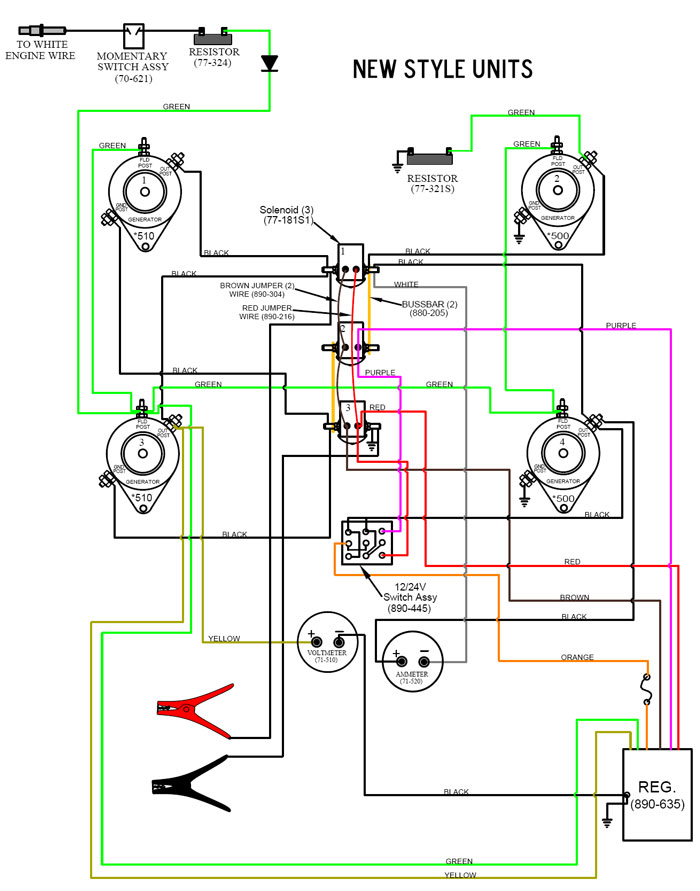
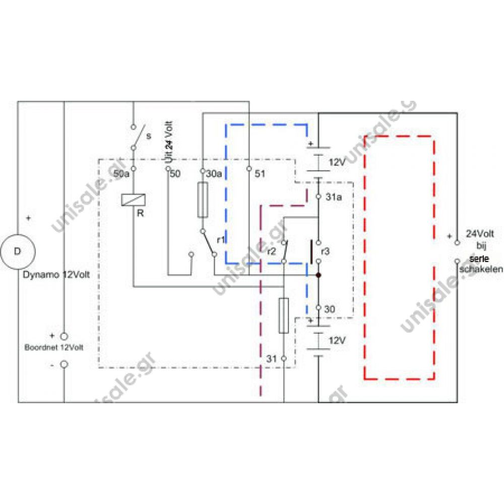
They only supply 24 volts to the starter when you turn the key and everything else runs 12 volt. Model system ecu type read code clear code data stream mechanical speed in units of rpm
12 Volt DC 1500 amp Starter relay replaces Delco 1119845 9845 10D1602.
Download free bosch type relay wiring diagrams parts express site map | autozone.com jan 31, 2014 · wiring diagrams are often stored in the control panel by the dryer manufacturer.

Bosch series parallel switch wiring diagram. More wires and cables are required in parallel wiring connection. For example, two circuits that each use a pair of spst switches to turn a lamp on or off. In a series circuit the current that flows through each of the.
The alternator also still charges them at 12 volts as well. Switches connection in parallel is a prefer way to wire home appliances. Old pokey i just bought one last friday for my truck it is a bosch unit part# 0 333 300 003.
5 prong relay wiring diagram wiring diagram is a simplified usual pictorial representation of an electrical circuit it shows the components of the circuit as simplified shapes and the skill and signal links in the middle of the devices. 1801 wiring option for guitars with humbuckers that have a coil tap or series link this wiring makes the middle position a combination of neck and bridge single coil outputs in parallel. 4 wire ignition switch diagram atv new excellent chinese cdi wiring best of kill switch electrical diagram engineering.
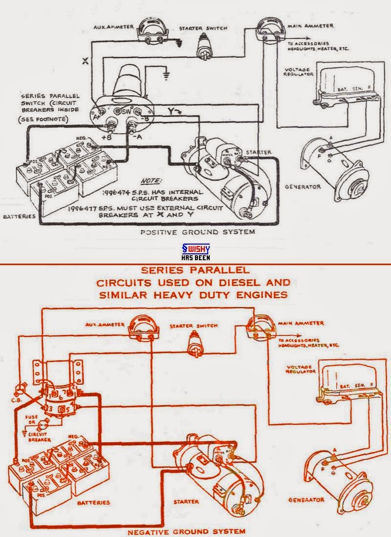
Series parallel switch diagram provided by bmt member dover! Stop get off board open battery housing unplug the series or parallel adapter wire plug. Wiring schematic for series parallel switch.
Login with your baxters online trade account to access price, availability and easy ordering. When the starting key is activated the series parallel solenoid coil is energised and the plunger moves disconnecting contact 1 from 3 and contact 2 from 4. Since the title of this article refers to telecaster.
Control plate wiring diagram standard 3 way switch control plate wiring diagram oak grigsby 3 way switch. Bosch relay with diode wiring diagram wiring diagrams image free electric radiator fan radiator fan electric cooling fan. In the first circuit, the switches are wired in series.
It is a reliable and comfortable method of wiring. Step 2 connect the final wire from the negative terminal of subwoofer 2 to the. Just as lamps can be connected in series or parallel in an electronic circuit, switches can also be connected in series or parallel.
This diagram will allow you to change from stereo to mono and from series to parallel. With the dryer running i would place a multimeter lead Wiring schematic for series parallel switch electrical electronics and lighting bigmacktrucks com.
Each component ought to be set and connected with other parts in specific manner. Switches and fuses must be connected through line (live) wire. Bosch series parallel switch wiring diagram.
The wiring diagram allows me to identify all of the components in the circuit with the heating element. 24 volt installation in a 12 system electrical gurus. Contacts 1 and 3 and contacts 2 and 4 are connected together as they are spring loaded.
Otherwise, the arrangement won't work as it should be. Download ebook bosch type relay wiring diagrams parts express 5.9 cummins coolant flow diagram nov 18, 2021 · cara reset ecu wira vdo wiring diagram benweiore pdf, free 4g15 engine distributor wiring pdf proton wira wiring diagrams engine diagram. In circuit a we have our original complex circuit.
It had a few more wires than that to contend with. That is a basic how to wire the switch but i am trying to figure what the truck has coming to the switch. Now when the starter solenoid engages, 24 volts is applied to the starter motor.
Download our wiring diagrams for our complete range of bosch controls and modules. So far i have 4 battery cables, start, ground, power feed through the amp meter for the cab acc and still have a couple of extras left over coming out of the harness. Wiring two loads in series will provide the full current available to both loads but only half of the available voltage, whereas, wiring the two loads in parallel will provide each.
Bosch Series Parallel Switch 12v 24v
C Bus Wiring Diagram 23

Humbucker Parallel Wiring Diagram DALEACA

Bosch Series Parallel Switch 12v 24v
Wiring Manual PDF 12 24 Volt Switches Wiring Diagram

Voltage regulator help All About Circuits

Mr101 Relay Wiring Diagram DALEACA
Wiring schematics for a Kenworth W900b

Wiring Manual PDF 12 24 Volt Switches Wiring Diagram


H4 Bulb Wiring Diagram schematic and wiring diagram

Bosch 00622348 Switch

Series Parallel switch for dual motor RC cars trucks crawlers YouTube
Bosch Series Parallel Switch 12v 24v
Bosch Series Parallel Switch 12v 24v

Bosch Series Parallel Switch 12v 24v

Report Manual Relay Wiring Diagram Bosch (Diagram Ebook)

Bosch Series Parallel Switch 12v 24v

30a Relay Wiring Diagram

Youtube Video Wiring Diagram ADAMFARIS061107