Damper Motor Wiring Diagram
Review job requirements and determine whether a plenum or appliance rated cable. To select a gas control wiring diagram, a motor and damper control wiring diagram, and an accessory wiring diagram if such accessories as fire stats, freeze stats, manual potentiometers etc.
Zone Control Replacing old 2wire spring damper with a high quality ecojay

Terminal m6 24vac to close damper.

Damper motor wiring diagram. Wiring a damper to a 3 wire thermostat and shown with an optional slave damper. Wire type and wire installation tips for most installations, 18 or 16 ga. To slave more than one motor together wire the motors in parallel.
Note the jumper wire required on the motor terminals 2 and 5. Don't forget, if the damper is a field or effikal, you can replace just the motor assembly which includes the safety interlocks. Multiple ard can be wired in parallel.
These diagrams are current at the time of publication, check the wiring diagram supplied with the motor. 3 and 4 for motor wiring hookups. Negative leg of the control signal.
Position indicator and service switch must be accessible to the user. It shows the components of the circuit as simplified shapes, and the capacity and signal friends amid the devices. 3 and 4 wiring diagrams.
If you are planing to replace the zone controller with smartzone , this diagram is not necessary. Review job requirements and determine whether a plenum. The nominal factory setting for auxiliary
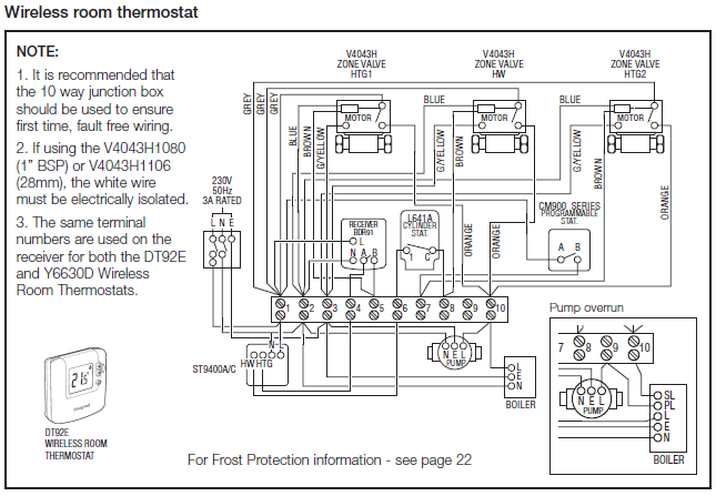
Wiring for damper actuators and control valves. 12 4 5 3 6 x z m6 m5 m4 m2 m1 closed open 24 volts note: Typical wiring diagrams wiring diagrams are shown for motor packs and dampers installed with power ventilator fan equipment with single speed motor.
When require more than five motors and isolation relay and additional transformers may be required. Wire type and wire installation tips for most installations, 18 or 16 ga. When using a slave motor, wire slave motor as shown in diagram on left.
Motor terminals on mastertrol mark iv, v, vii, viii, x, xxx, and xxxi. When operating more than one damper motor per zone, consult specific wiring diagrams. Note the jumper wire required on the motor terminals 2 and 5.
When any zone is calling, that damper will be in the open position. M436a/m836a,b damper motors application m436a/m836a,b damper motors are spring return (sr) motors used for residential and light commercial applications in series 40 and series 80 circuits. The damper will open when the fan is on and close when the fan is off.
A total of five (5) motors should be on one 40va transformer. The installer must fill in the label on the side of the motor assembly cover. The damper motor has a 24 vac, 50/60 cycle, 6 va rating.
The damper then returns to its normal position. Wiring 120 v ac wiring diagrams auxiliary switch wiring diagram 3900 dr. A minimum clearance of 6 inches (153mm) between the damper device and combustible construction must be maintained and there must be provisions for access and service of the damper device.
Jumper wire control panel control panel a single rectangular damper motor is wired. Two screws, the wiring harness plug and you're done. Wiring a damper to a 5 control panel.
Items used/shown in this video:weil mclean vent damper assembly: Terminal m4 24vac to open damper. Refer to the motor manufacturer's data on the motor for wiring diagrams on standard frame ex e, ex d etc.
Cable works well with belimo actuators. Operation wiring use 3 conductor wire from each zone damper motor terminal to the corresponding terminals on the stms or stex control panels. Cable works well with belimo actuators.
Inst maint & wiring.qxd 5/03/2008 10:02 am page 6 One 24vac, 40va transformer can power up to five (5) damper motors. @pmj has a good point.
Wiring a motor see fig. Consult wiring diagrams for damper types. For dje models which do not include a blower section, only a gas control wiring diagram is required and an accessory diagram if used.
Ge or general electric and emerson (to name a few) produce the variable speed ecm motors for the hvac industry.

Pin on Control wiring

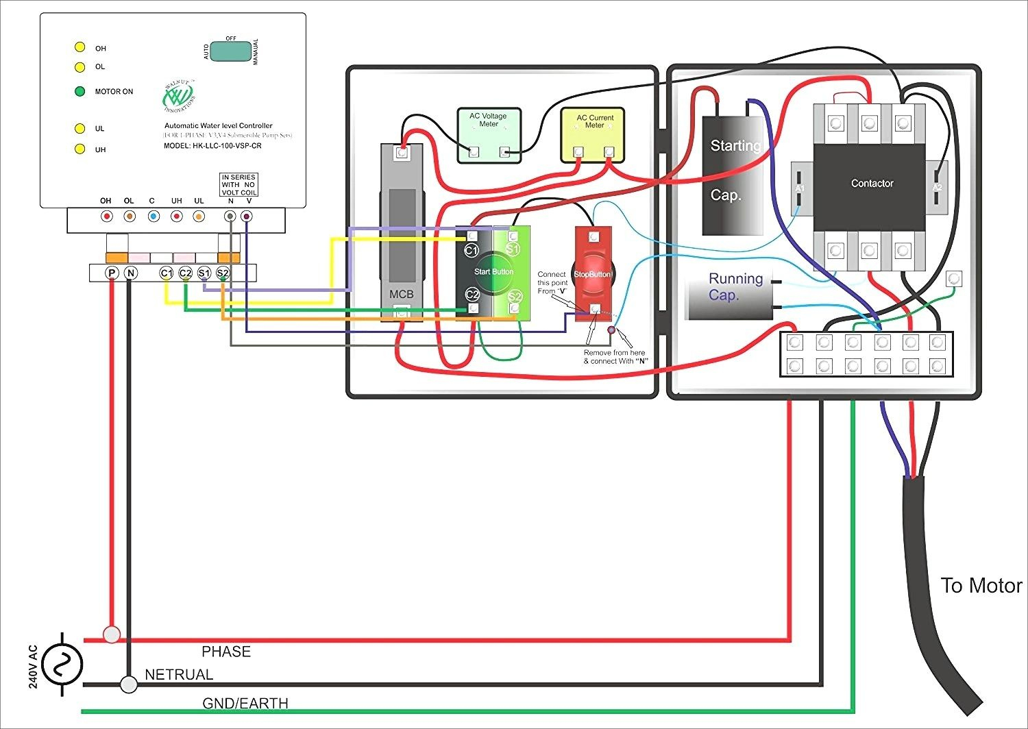
Submersible Motor Control Box Wiring Single Phase water Pump Water Pump YouTube

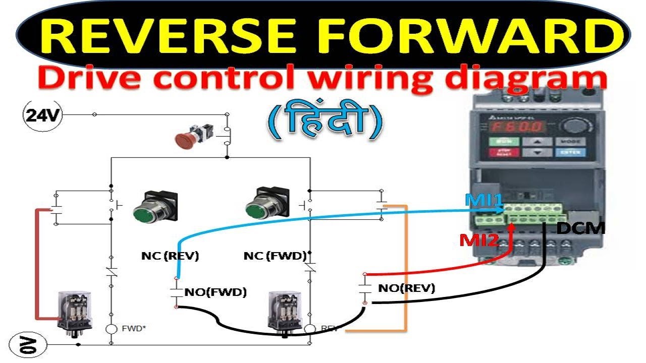
A forward reverse starter with timer for 3 phase motor diagram. In the forward reverse timer

Collection Of Belimo Lf24 Sr Wiring Diagram Sample
Inverter Drive Motor Connection Home Wiring Diagram
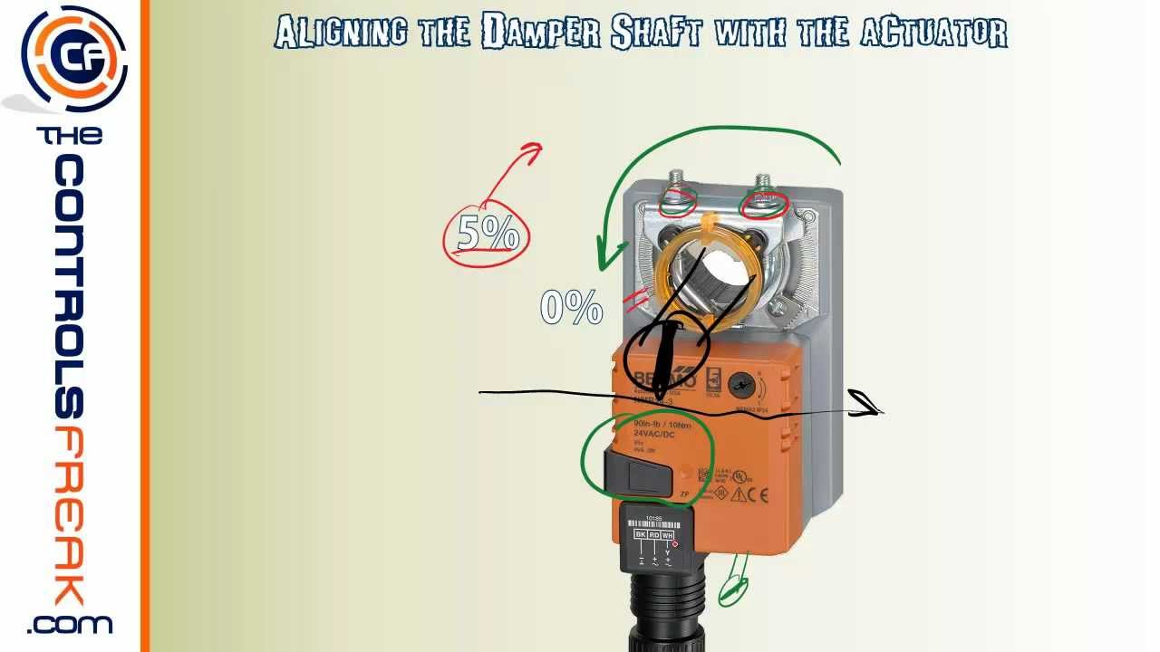
Quick Tip To Make Sure Your Belimo Actuator Seals Your Damper Closed YouTube

Gvd 6 Wiring Diagram Free Wiring Diagram

Fire Smoke Damper Wiring Diagram Collection

Start Run Capacitor Wiring Diagram And Kwikpik Me Motor Circuit 1440 Best Of Starting มอเตอร์

Forward Reverse Motor Control Diagram For 3 Phase Motor Electrical Online 4u Electrical
24 and 120 VAC Round Damper Wiring Instructions FAMCO

Electrical and Electronics Engineering Types of Motor Control Schematics!! Electrical circuit

3 Phase Motor Wiring Diagrams NonStop Engineering Electrical circuit diagram, Power supply
Single Phase Motor Wiring Diagram Forward Reverse Cadician's Blog

What is Soft Starter? Its Working, Diagram and Applications Electricity, Circuit diagram

Razor Wiring Diagram With Images Electric Scooter Razor Simple To Read Wiring Diagram For A Boat
Trol A Temp Zone Damper Wiring Diagram
3 Phase Contactor Wiring Diagram Start Stop Cadician's Blog

Belimo Damper Actuator Wiring Diagram