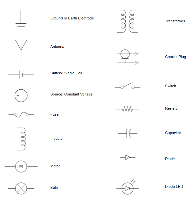
Plc Wiring Diagram Symbols
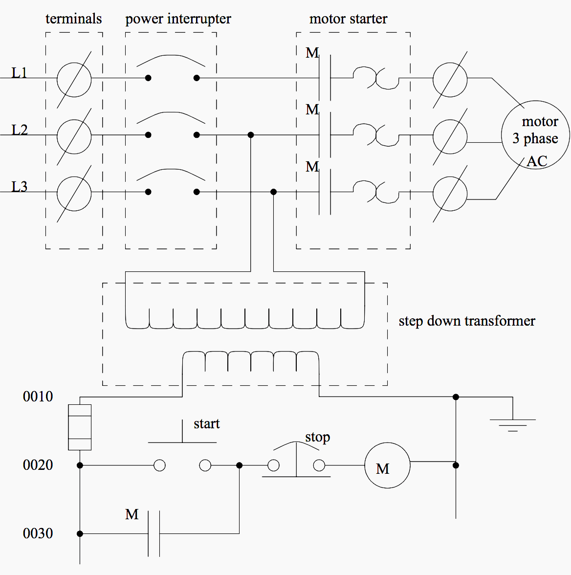
The three phases are then connected to a power interrupter. How to create electrical diagram?

Plc Wiring Diagram Symbols Pdf
This system uses 3 phase ac power (l1, l2 and l3) connected to the terminals.

Plc wiring diagram symbols. The below figure is an overview of one. Line diagrams provide a fast, easy understanding of the connections and In fact, they only show symbols made up of ascii characters like this:
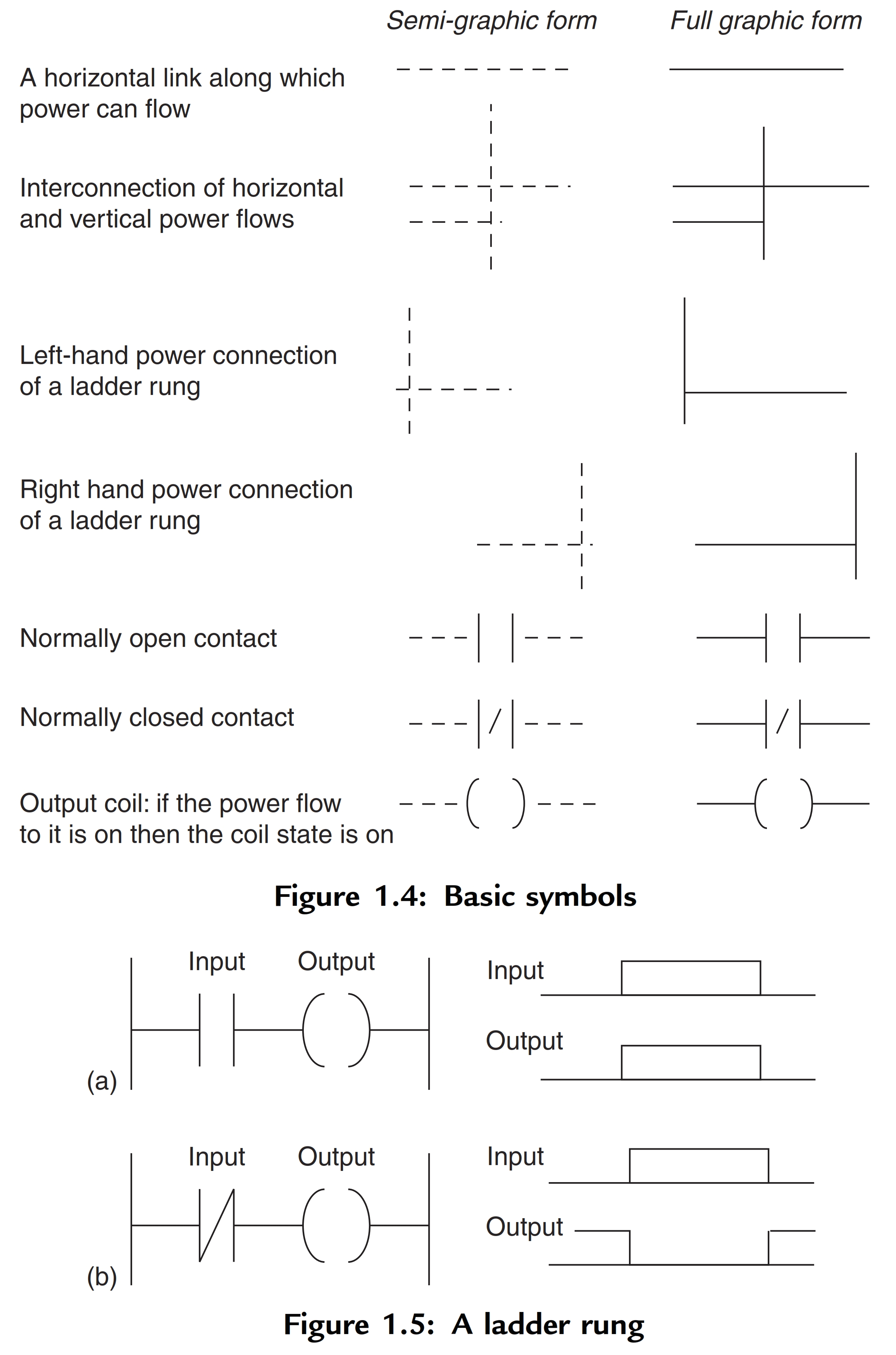
As electrical panels are what will contain control systems, panel wiring diagrams are commonly encountered by plc technicians and engineers. Wordsun.com) we can redraw this diagram in a different way, using two vertical lines to represent the input power rails and stringing the rest of the circuit between them. Line diagrams a line (ladder) diagram is a diagram that shows the logic of an electrical circuit or system using standard symbols.
A wiring diagram usually provides info about the relative. Electrical panel wiring diagrams are used to outline each device, as well as the connection between the devices found within an electrical panel. Wiring diagram plc mitsubishi bookingritzcarlton info programmable logic controllers ladder logic plc programming plc wiring diagrams diagram guide pdf drawings.
Elementary diagram connections wire numbering. Failsafe wiring practice is one of those topics that separates control system designers and electricians from other technical specialties. This sample was created in conceptdraw diagram diagramming and vector drawing software using the computer and networks solution from computer and networks area of conceptdraw solution park.
Although electrical panels may not be overly complex from the first glance, a lot of. It wasn't so easy to create electrical symbols and electrical diagram as it is now with electrical diagram symbols offered by the libraries of electrical engineering solution from the industrial engineering area at the conceptdraw solution park. Dashed lines indicate a single purchased component.
Despite different standards of these types of drawings youll learn using. It is the easiest way to add more ethernet devices into the network. Double break single break spst, n.c.
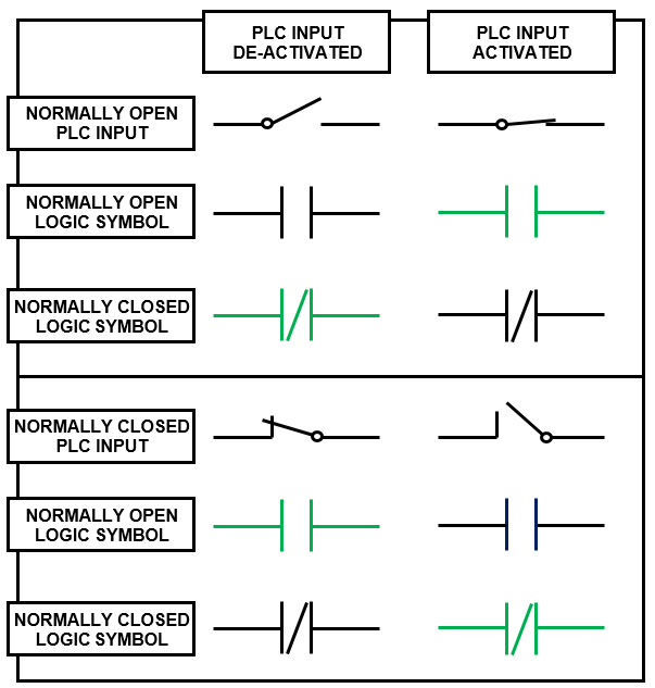
Plc ladder logic symbols the symbols are ladder logic instructions the plc scans (executes) the symbols: Standard wiring diagram symbols if a line touching another line has a black dot, it means the lines are connected. Autocad electrical plc wiring diagram.
Most symbols suited for a wiring diagram look. Each component ought to be set and linked to. This solution provides 26 libraries which contain 926.
When unconnected lines are shown crossing, you can see a line hop. Plc panel wiring diagram pdf sample. The modules generate in various different graphical styles all without a single complete io module library symbol resident on the system.
The diagram shows the circuit for switching on or off an electric motor. All you need is a powerful software. In the daisy chain network one computer is connected to.
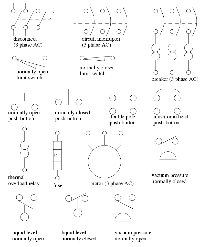
Table 1 standard elementary diagram symbols (cont'd) battery bell annunciator buzzer horn, alarm, siren,etc. Double break single break spdt double break single break dpst, 2 n.o. To begin understanding how to read and.
A wiring diagram is an electrical print that shows connections of all components in a piece of equipment.a schematic diagram is a type of drawing that illustrates the electrical connections and functions of specific circuit arrangements with graphic symbols.a ladder diagram is a diagram that explains the logic of the electrical circuit or system using standard nema or iec. To understand how to read ladder wiring diagrams, let's start with a simple electrical schematic consisting of a power supply, switch, and light, then you will move on to our control panel sample wiring diagrams. Electrical wiring diagram plc autocad electrical plc wiring diagram.
For example if you see a number like 366 beside or below a component in plc wiring diagram. An example of a wiring diagram for a motor controller is shown in figure 1. A daisy chain is the simple computer network.
Note that symbols are discussed in detail later). Figure 1b shows the result. Plc digital signals wiring techniques.
A line diagram is used to show the relationship between circuits and their components but not the actual location of the components. Ina process plant, on/off control is done through the plc or dcs. Double break single break dpst, 2 n.c.
A circuit diagram is the key to electrical & electronic equipment and systems
Modernizing An Old Hardwired Relay Logic With Modern PLC System EEP

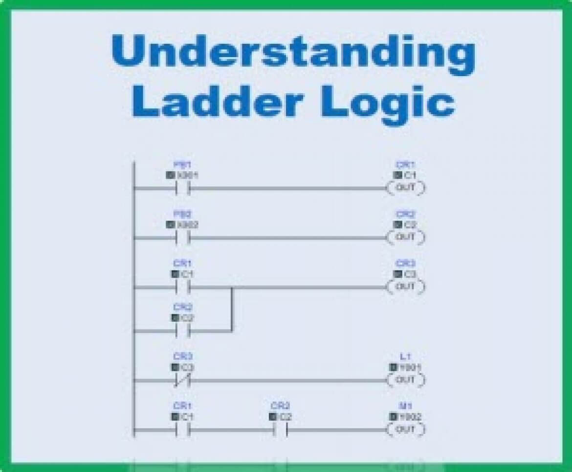
The PLC ladder diagram. Download Scientific Diagram
Introduction to PLC Ladder Diagrams Free PLC Tutorials Download

Most commonly used relay instructions used in PLC programming are as shown in the table below

Ladder Diagrams And The PLC EEP Ladder logic, Electrical circuit diagram, Plc programming
Plc Wiring Diagram Symbols

Plc Panel Wiring Diagram, http//bookingritzcarlton.info/plcpanelwiringdiagram/ Electrical
Plc Wiring Diagram Symbols Pdf Sunita News
Electrical Diagram Symbols Plc Wiring Diagram Symbols Plc Programmable Logic Controllers Plc
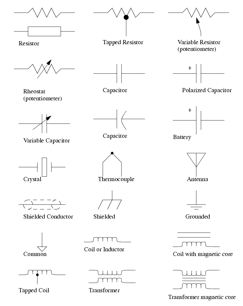
Common Schematic Symbols Wiring Library

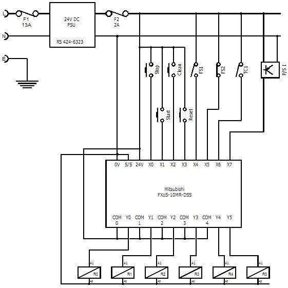
Typical Plc Wiring Diagram
Basic electrical design of a PLC panel (Wiring diagrams) EEP
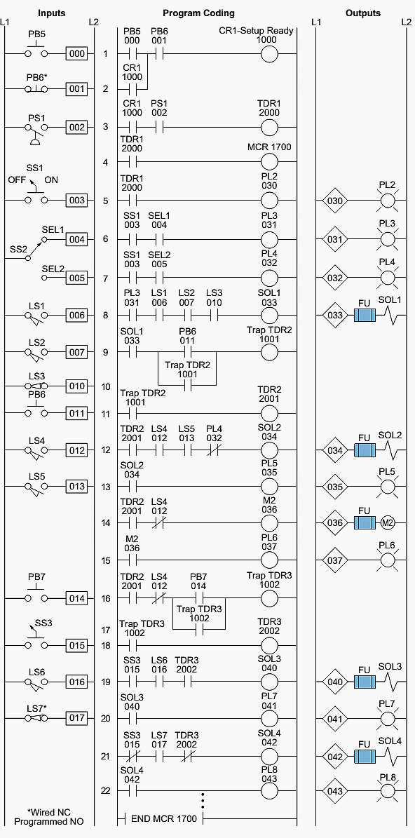
Ladder Logic Programming Examples Ladder Logic World
eBook Automating Manufacturing Systems; with PLCs

Plc Wiring Diagram Symbols Pdf BLANKETSTEALER

45+ Plc Control Panel Wiring Diagram Pictures

How to Convert a Basic Wiring Diagram to a PLC Program YouTube

Plc Wiring Diagram Symbols Pdf